
In the AEC industry, drawings are not just sheets with lines, dimensions, and notes. They are the communication bridge between design intent, site execution, manufacturing, and final installation. When a project moves from design to construction, two drawing types often come into discussion: shop drawings and fabrication drawings.
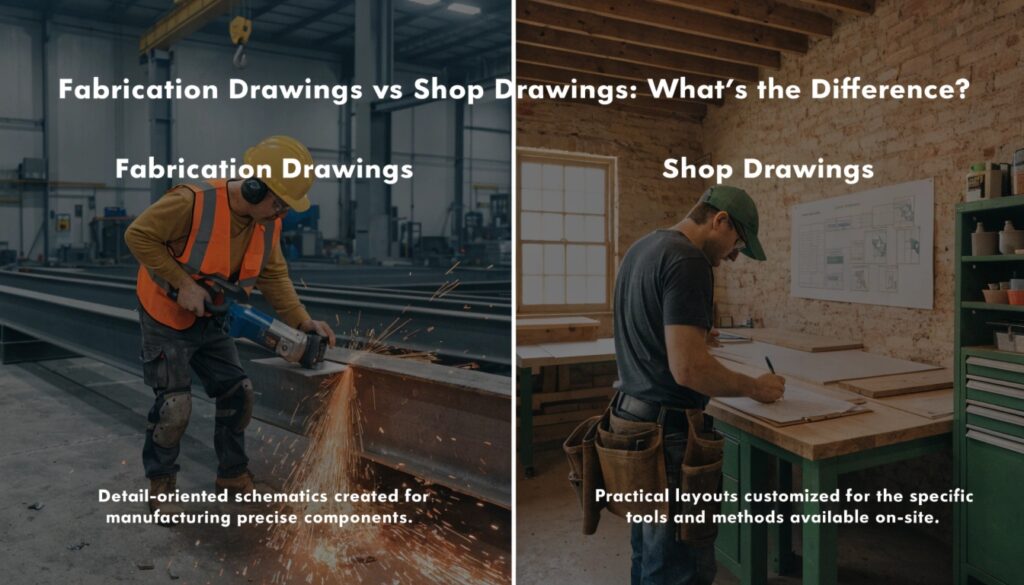
Shop drawings explain how a component will be built and installed for a specific project, while fabrication drawings go deeper into the actual manufacturing details required to cut, bend, weld, drill, assemble, or produce that component.
For contractors, architects, engineers, BIM teams, fabricators, and project managers, understanding this difference can reduce RFIs, avoid rework, improve coordination, and help construction teams move with better clarity.
Key Takeaways
Shop drawings are usually prepared for review, coordination, and approval before work begins on site or in the workshop. They show how the design will be translated into project-specific construction details.
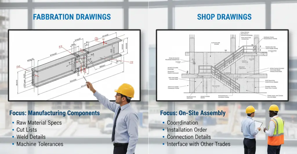
Fabrication drawings are more detailed and production-focused. They tell the fabricator exactly how to manufacture or assemble a component.
Shop drawings are commonly submitted to architects, consultants, engineers, or general contractors for approval. Fabrication drawings are mainly used by fabricators, workshop teams, CNC operators, welders, installers, and production teams.
Both drawings are important. Shop drawings support coordination and approval, while fabrication drawings support accurate manufacturing and execution.
In BIM-based workflows, both drawing types can be extracted from coordinated 3D models, which improves accuracy, reduces clashes, and keeps site and fabrication teams aligned.
What Are Shop Drawings?
Shop drawings are detailed project-specific drawings prepared by contractors, subcontractors, suppliers, or fabricators to show how a particular element will be built, installed, assembled, or coordinated within the actual project.
These drawings are not the same as design drawings issued by architects or engineers. Design drawings show the overall intent, layout, specifications, and performance requirements. Shop drawings take that intent and convert it into practical construction details.
For example, an architectural drawing may show the location and design intent of a staircase. A shop drawing will show the staircase dimensions, materials, connections, railing details, fixing points, levels, finishes, and how it fits with surrounding walls, slabs, and structural elements.
In MEP projects, shop drawings may show duct routing, pipe layouts, hanger locations, equipment connections, sleeve openings, valve positions, access panels, and clearance zones. In steel projects, they may show member sizes, connection details, bolt arrangements, and erection references.
What Do Shop Drawings Include?
Shop drawings usually include a combination of technical and coordination information. The exact content depends on the project type and trade, but most shop drawings include:
| Shop Drawing Element | Purpose |
| Plans, sections, and elevations | Show component location and relationship with other building systems |
| Dimensions and levels | Confirm exact sizes, heights, offsets, and installation positions |
| Material details | Identify approved materials, finishes, grades, and specifications |
| Connection details | Show how elements connect to structure or other systems |
| Installation notes | Guide site teams during execution |
| Coordination references | Help avoid clashes with architectural, structural, and MEP systems |
| Approval notes | Track consultant, contractor, or client review status |
In India, shop drawings are heavily used in commercial buildings, hospitals, metro projects, airports, industrial facilities, data centers, residential towers, and infrastructure projects. They help reduce confusion between design consultants, contractors, site engineers, and subcontractors.
What Are Fabrication Drawings?
Fabrication drawings are highly detailed drawings used to manufacture, cut, bend, weld, drill, assemble, or produce building components in a workshop, factory, or fabrication yard.
They are more production-focused than shop drawings. While shop drawings explain how a component fits into the project, fabrication drawings explain how that component should be physically made.
For example, a shop drawing for a steel beam may show where the beam is located, how it connects to columns, and what bolts are required. A fabrication drawing for the same beam will show cutting length, hole diameter, plate thickness, weld size, edge preparation, part marks, material grade, and assembly sequence.
In MEP prefabrication, fabrication drawings may show spool pieces, pipe lengths, bend angles, flange details, support points, valve tagging, insulation clearance, and welding requirements. In rebar work, fabrication drawings may show bar bending schedules, lap lengths, hook details, cutting lengths, and bar marks.
Fabrication drawings are mostly used by people who physically produce the component. That includes fabricators, welders, machine operators, CNC teams, workshop supervisors, QA/QC teams, and sometimes installation crews.
What Do Fabrication Drawings Include?
Fabrication drawings contain exact manufacturing information. These drawings leave very little room for interpretation because the workshop team depends on them for production accuracy.
| Fabrication Drawing Element | Purpose |
| Part marks and assembly marks | Identify each component clearly during production and installation |
| Cutting lengths | Guide cutting machines and workshop teams |
| Hole sizes and locations | Ensure accurate drilling and bolting |
| Weld symbols and weld sizes | Guide welders and inspection teams |
| Plate, pipe, duct, or bar details | Define the actual physical component |
| Material grade and thickness | Ensure compliance with specifications |
| Bend angles and profiles | Support accurate bending or shaping |
| Tolerances | Control production quality |
| Bill of materials | List all required materials and quantities |
Fabrication Drawings vs Shop Drawings: Main Difference
The biggest difference between shop drawings and fabrication drawings is the level of detail and purpose.
Shop drawings are created for project coordination, design review, approval, and installation understanding. Fabrication drawings are created for manufacturing and production.
| Point of Difference | Shop Drawings | Fabrication Drawings |
| Main Purpose | Show how a component will be built and installed in the project | Show how a component will be manufactured or fabricated |
| Level of Detail | Detailed, but usually approval and coordination-focused | Highly detailed, production and workshop-focused |
| Main Users | Architects, consultants, engineers, contractors, site teams | Fabricators, welders, CNC operators, workshop teams, QA/QC teams |
| Prepared By | Contractors, subcontractors, suppliers, BIM teams, fabricators | Fabricators, detailing teams, production teams, BIM/detailing specialists |
| Approval Requirement | Usually submitted for consultant or client approval | Often prepared after shop drawing approval for fabrication use |
| Focus Area | Design intent, coordination, installation, project compliance | Cutting, drilling, welding, bending, assembly, manufacturing |
| Common Trades | MEP, façade, steel, millwork, HVAC, plumbing, electrical, architectural works | Steel, rebar, ductwork, piping, spools, façade panels, precast, metal works |
| Output Use | Site installation and coordination | Workshop production and fabrication |
Why Shop Drawings Are Important in Construction
Shop drawings bring design intent closer to real construction. They act as a bridge between consultants’ drawings and site execution.
In large Indian construction projects, small drawing errors can lead to major delays. A wrongly coordinated duct route, incorrect sleeve location, or missed beam penetration can create site conflicts. Shop drawings help catch these issues before installation starts.
They also reduce dependency on verbal instructions. Instead of relying on assumptions, site engineers, supervisors, and subcontractors can follow a clear approved drawing.
Why Fabrication Drawings Are Important
Fabrication drawings protect the accuracy of production. When a component is manufactured in a factory or workshop, the team needs exact information. Even a small mistake in cutting length, hole placement, weld detail, or material thickness can lead to rejection, rework, or installation failure.
Fabrication drawings help avoid these problems by giving clear production instructions.
Fabrication drawings also help in material planning. They support quantity control, procurement, waste reduction, and workshop sequencing. For contractors working on tight timelines, this can directly improve project productivity.
Are Shop Drawings and Fabrication Drawings the Same?
No, they are not the same, but they are closely connected.
In many projects, a shop drawing may contain enough detail for simple fabrication. That is why some teams casually call it a fabrication drawing. However, in professional AEC workflows, especially for steel, MEP, façade, precast, and modular construction, fabrication drawings are usually more detailed and production-specific.
A shop drawing says, “This is how the component fits into the project.”
A fabrication drawing says, “This is exactly how the component must be made.”
When Are Shop Drawings Prepared?
Shop drawings are usually prepared after the design drawings are issued and before actual installation or fabrication starts.
The common workflow looks like this:
- Architect or engineer issues design drawings.
- The contractor or subcontractor reviews the design.
- BIM/detailing team prepares shop drawings.
- Shop drawings are submitted for approval.
- Consultant, client, or general contractor reviews the drawings.
- Comments are resolved through revisions.
- Approved shop drawings are used for coordination, installation, or fabrication planning.
Shop drawings should ideally be prepared before site work begins. If teams wait too long, site execution starts based on assumptions, which increases the chances of clashes, rework, and delay.
When Are Fabrication Drawings Prepared?
Fabrication drawings are usually prepared after the shop drawings are approved or after the design is fully coordinated.
This is important because fabricating components before approval can be risky. If a consultant later changes a connection detail, duct route, pipe size, or equipment location, the already fabricated item may become unusable.
The common workflow is:
- Shop drawings are prepared and coordinated.
- Drawings are submitted for approval.
- Consultant or client comments are resolved.
- Approved drawings are used as the base.
- Fabrication drawings are prepared.
- Workshop team manufactures the component.
- QA/QC checks the fabricated item.
- Component is delivered and installed on site.
This workflow reduces wastage and helps the project team avoid costly rework.
Role of BIM in Shop Drawings and Fabrication Drawings
BIM has changed how shop drawings and fabrication drawings are produced. Earlier, many drawings were prepared manually in 2D CAD. Today, contractors and consultants use BIM models to generate coordinated drawings with better accuracy.
A BIM model can combine architectural, structural, and MEP systems in one digital environment. This allows the team to identify clashes, check clearances, validate levels, and coordinate installation before work reaches the site.
For shop drawings, BIM helps produce coordinated plans, sections, elevations, and installation details. For fabrication drawings, BIM can support spool drawings, hanger layouts, duct fabrication details, steel detailing, rebar schedules, and quantity extraction.
BIM also improves communication between site and fabrication teams. When the model is properly developed, drawings become more reliable because they come from a coordinated source instead of disconnected 2D files.
Common Mistakes in Shop Drawings
Many project delays happen because shop drawings are prepared without enough coordination or practical site understanding.
One common mistake is copying design drawings without adding real construction details. A shop drawing should not simply repeat the consultant’s drawing. It should explain how the work will actually be executed.
Another mistake is ignoring other trades. For example, an HVAC duct route may look fine in isolation, but it may clash with fire pipes, cable trays, beams, or false ceiling levels. This is why coordination is essential before submission.
Incomplete dimensions are also a major issue. Site teams need clear levels, offsets, centerlines, and references. If the drawing leaves too much to interpretation, execution quality suffers.
Common Mistakes in Fabrication Drawings
Fabrication drawings demand precision. A small error can directly affect production.
One major mistake is missing part numbers or assembly marks. Without proper tagging, workshop teams may fabricate components correctly but struggle to identify where each piece goes during installation.
Another common issue is incorrect material specification. If the drawing does not mention the correct grade, thickness, size, or finish, the wrong material may be used.
Missing weld details, bolt sizes, hole diameters, and cutting lengths can also create serious problems. Fabrication teams need exact information, not assumptions.
In MEP fabrication, incorrect spool lengths or wrong connection details can delay installation. In steel fabrication, wrong hole alignment or plate size can stop the erection work on site.
Good fabrication drawings should be production-ready, checked, and aligned with approved shop drawings.
Which Drawing Comes First: Shop Drawing or Fabrication Drawing?
In most construction workflows, shop drawings come first, followed by fabrication drawings.
The shop drawing is prepared for review and approval. Once it is approved, the fabrication drawing is developed for production.
However, in some fast-track projects, both may be developed almost together. This usually happens when the project schedule is tight and the contractor wants to save time. But even in that case, fabrication should not start until the necessary approvals and coordination checks are completed.
Design Drawing → BIM Coordination → Shop Drawing → Approval → Fabrication Drawing → Manufacturing → Delivery → Installation
Shop Drawings vs Fabrication Drawings in Different Trades
Structural Steel : In steel construction, shop drawings show member layouts, connection details, erection references, and structural coordination. Fabrication drawings show cutting lengths, plates, bolts, holes, welds, stiffeners, and part marks.
MEP Services: In MEP, shop drawings show coordinated layouts for HVAC, plumbing, fire protection, electrical, and mechanical systems. Fabrication drawings show duct pieces, pipe spools, supports, hangers, bends, flanges, and production details.
Rebar Detailing: For reinforcement work, shop drawings show bar placement, spacing, and structural intent. Fabrication drawings or bar bending schedules show exact bar shapes, cutting lengths, bending details, lap lengths, and bar marks.
Façade and Curtain Wall: Façade shop drawings show panel arrangement, elevations, fixing details, interface with structure, and waterproofing conditions. Fabrication drawings show mullion cuts, bracket details, glass panel sizes, gasket details, and factory assembly information.
Millwork and Interior Fit-Out: Millwork shop drawings show furniture layouts, cabinetry details, finishes, and installation conditions. Fabrication drawings show panel sizes, joinery details, cutting lists, hardware placement, and assembly instructions.
Best Practices for Better Shop and Fabrication Drawings
A strong drawing workflow starts with updated design information. Before preparing any drawing, the team should check the latest architectural, structural, MEP, and specification documents.
The second step is coordination. Shop drawings should be checked against other trades before submission. BIM coordination can make this process much stronger because clashes are easier to detect in 3D than in isolated 2D drawings.
The third step is clear annotation. Dimensions, levels, tags, materials, connection details, and notes should be easy to read. A drawing that looks complicated but does not guide the user properly can still fail on site.
The fourth step is proper review. Shop drawings should be reviewed for design intent and coordination. Fabrication drawings should be reviewed for manufacturability and production accuracy.
The final step is revision control. Every drawing should have a clear revision number, date, status, and reference. This prevents teams from working on outdated drawings.
Final Comparison: Shop Drawings vs Fabrication Drawings
| Question | Shop Drawings | Fabrication Drawings |
| What do they explain? | How the component fits and installs in the project | How the component is manufactured |
| Are they used for approval? | Yes, usually | Not always; mostly used for production |
| Are they used on site? | Yes | Sometimes, mainly for assembly reference |
| Are they used in workshops? | Sometimes | Yes, heavily |
| Are they trade-specific? | Yes | Yes |
| Do they need BIM coordination? | Highly recommended | Recommended, especially for prefab and modular work |
| Which is more detailed? | Detailed for construction and coordination | More detailed for production and manufacturing |
Conclusion
Fabrication drawings and shop drawings both play a major role in construction, but they serve different purposes.
Shop drawings help the project team review, coordinate, approve, and install building components correctly. They translate design intent into project-specific construction information.
Fabrication drawings help the workshop or manufacturing team produce the component accurately. They include exact production details such as cutting lengths, welds, holes, bends, material grades, and assembly marks.
For modern AEC projects, especially those using BIM, prefabrication, modular construction, steel detailing, MEP coordination, and façade systems, both drawing types are essential. When prepared properly, they reduce rework, improve quality, support faster approvals, and help teams deliver projects with better control.
FAQs
1. What is the main difference between shop drawings and fabrication drawings?
The main difference is purpose. Shop drawings are prepared for project coordination, approval, and installation understanding. Fabrication drawings are prepared for manufacturing and production. Shop drawings show how an element fits into the project, while fabrication drawings show how that element should be made.
2. Are fabrication drawings more detailed than shop drawings?
Yes, fabrication drawings are usually more detailed because they include production-level information. They may show cutting lengths, hole sizes, weld details, bend angles, part marks, material grades, and assembly instructions. Shop drawings are detailed too, but they focus more on coordination, installation, and design approval.
3. Who prepares shop drawings in construction?
Shop drawings are usually prepared by contractors, subcontractors, suppliers, BIM modelers, drafting teams, or trade specialists. For example, an MEP contractor prepares MEP shop drawings, while a façade contractor prepares curtain wall shop drawings.
4. Who uses fabrication drawings?
Fabrication drawings are mainly used by fabricators, welders, CNC operators, workshop supervisors, production teams, QA/QC inspectors, and assembly teams. These drawings guide the actual manufacturing or fabrication process.
5. Can BIM be used for shop drawings and fabrication drawings?
Yes. BIM can be used to create both shop drawings and fabrication drawings. A coordinated BIM model helps generate accurate layouts, sections, details, spool drawings, quantity schedules, and fabrication-ready outputs. It also helps reduce clashes and improves communication between design, site, and fabrication teams.